SNACKY CB 35 · VK4OMG
Snacky’s Homemade Antennas
Homemade CB and amateur antenna designs, with measurements, connections and tuning notes.
Download the antenna build sheetNew: 20–10 metre fan dipole · full build guide
New: three-element 10 / 11 metre Yagi · full build guide
SNACKY’S HOMEMADE ANTENNAS · METRIC WORKSHOP GUIDE
Three-element Yagi beam · 10 & 11 metres
One adjustable aluminium beam, two marked band settings.
A horizontal, full-size beam with a reflector behind the feed element and a director in front. Aim the director towards the station you want to work. The 11 m setting targets 27.355 MHz; the 10 m setting targets 28.500 MHz for amateur SSB.
Design status: This is a proposed adjustable adaptation of 19DX348’s published 27.555 MHz, three-element OWA Yagi. Dimensions below are frequency-scaled starting geometry, rounded to millimetres. Keeping readily available 25 / 22 mm tubes rather than scaling their diameters makes this an approximation. These two settings have not been simulated or field-tested by the club. Verify impedance, bandwidth and radiation pattern before treating the design as final. It is not a guaranteed simultaneous dual-band beam, and does not promise coverage of the whole 28–29.7 MHz band.
1. Top view · 11 m starting setting
2. Measurements · all dimensions in mm
| Dimension | 11 m · 27.355 MHz | 10 m · 28.500 MHz |
|---|---|---|
| Reflector total | 5,641 | 5,414 |
| Driven element total, including 20 mm gap | 5,298 | 5,086 |
| Director total | 4,795 | 4,602 |
| Central 25 mm section span, including gap on driven element | 3,022 | 2,901 |
| Reflector → driven element centres | 1,309 | 1,257 |
| Reflector → director centres | 3,022 | 2,901 |
| Driven → director centres | 1713 | 1644 |
Use a 3,400 mm physical boom. Mark the reflector centre 150 mm from its rear end. For 11 m, mark the driven centre at 1,459 mm and director at 3,172 mm from that same end. For 10 m, use 1,407 mm and 3,051 mm. Clamp mounts must be movable; change element lengths and both forward mount positions when changing settings.
| Part | 11 m · 27.355 MHz | 10 m · 28.500 MHz |
|---|---|---|
| Reflector / director 25 mm centre tube, each side | 1511 | 1450.5 |
| Driven 25 mm tube, each half from gap edge to diameter step | 1501 | 1440.5 |
| Reflector 22 mm tip | 1309.5 | 1256.5 |
| Driven 22 mm tip | 1138 | 1092.5 |
| Director 22 mm tip | 886.5 | 850.5 |
The 10 m central section is 121 mm shorter overall: shift each diameter transition inward 60.5 mm. An adjustable centre arrangement must preserve electrical contact on each half while allowing that change. Simply sliding only the 22 mm tips approximates a different taper and needs fresh modelling / tuning. For the straightforward build, use interchangeable central tube sets for the two bands.
3. Materials and cut list
- One 3.4 m aluminium boom; 50 × 50 × 3 mm square tube is a candidate workshop size, not an engineered wind-load specification.
- 25 mm OD aluminium central tubing, about 1.5 mm wall, and compatible 22 mm OD tips. Check actual fit before purchase; nominal sizes and tolerances vary. Use straight antenna-grade tubing, deburr every cut, and use thin-wall tips only if mechanically suitable.
- For the 11 m starting assembly: two continuous 3,022 mm central tubes for reflector/director; two 1,501 mm tubes for the driven halves. An insulating centre support holds the 20 mm gap.
- Six 22 mm tip blanks: two 1,560 mm reflector tips, two 1,390 mm driven tips, two 1,140 mm director tips. These allow at least 200 mm joint engagement plus adjustment at the listed settings. Confirm the actual fit and required structural overlap before cutting.
- For interchangeable 10 m central sections: two continuous 2,901 mm tubes, plus two 1,440.5 mm driven halves. The same tip blanks can be reused and clamped at the corresponding exposed lengths.
- Three insulated element saddles, stainless U-bolts and plates, six tip clamps, an insulating driven-element plate, UV-resistant hardware, and a suitable mast-to-boom mounting plate.
- A weatherproof 1:1 current balun/choke specified for 27–30 MHz and your actual power and duty cycle, with two balanced terminals; 50 Ω outdoor coax and suitable connectors.
- Tape measure, callipers, saw, deburring tool, drill, multimeter, calibrated antenna analyser/VNA and SWR meter. Use aluminium-compatible joint compound and weatherproof connector tape.
4. Build the beam
- Make the boom marks. Choose the 11 m setting first. Mark all positions from one rear-end datum. Set every element perpendicular to the boom and parallel to the others.
- Assemble the parasitic elements. Insert the 22 mm ends into the 25 mm central tube and set their exposed lengths from the table. Maintain at least 200 mm overlap as a starting construction allowance; increase if required by the structural design. Keep left and right sides equal. Clean contact surfaces and clamp firmly without crushing the tubes.
- Build the split driven element. Use a rigid UV-resistant insulating centre plate. Hold two 1,501 mm central tubes with exactly 20 mm between their inner ends. Nothing metallic may bridge that gap. Fit both driven tips to 1,138 mm exposed each for an end-to-end span of 5,298 mm including the gap.
- Isolate the elements from the boom. Use nonconductive saddles for this proposed build to avoid direct through-boom electrical contact and its corrections. Keep metal mounting hardware compact. Holder dielectric and nearby metal still influence tuning.
- Mount and balance it. Place the mast clamp near the assembly’s centre of gravity, clear of the feedpoint. Route the coax along the boom towards the mast with strain relief. Support sagging elements with nonconductive guys if needed; recheck tuning after support changes.
- Record two settings. Mark tip insertion and clamp positions only after tuning. Disconnect the transmitter and lower the beam before changing bands. Change all three element lengths, central tube sets and both forward element positions.
5. Feedpoint · direct balanced feed
Connect one balanced terminal of the 1:1 current balun to the left driven half and the other to the right half, using short, symmetrical connections. Connect the coax to the balun’s input connector. Reflector and director have no feed wires. Do not link the two driven halves or connect either to the boom.
The original OWA design is intended for approximately 50 Ω direct feed. That impedance must be checked on this adaptation; a 1:1 balun suppresses common-mode current but does not transform a substantially different impedance into 50 Ω. A 4:1 balun or gamma match is not specified. If measurements remain far from 50 Ω, remodel the actual taper, mounts and spacing rather than adding a guessed match.
Provide independent coax strain relief and weatherproof the connector and terminals. Before connecting the balun, check that the driven halves are isolated from each other and from the boom, and that each tube joint has good continuity. The balun’s own DC readings depend on its construction.
6. Tuning and commissioning
- Use an analyser with the transmitter disconnected. Start with the beam in a clear horizontal test installation, ideally at least about 5.5 m above ground if the support is safe. Final height, roof, mast and nearby metal can change the results; repeat measurements in the final installation.
- For 11 m, sweep approximately 26.8–28.0 MHz and record SWR, resistance and reactance at 27.355 MHz. For 10 m, sweep the intended amateur operating window around 28.500 MHz. Wider analyser sweeps are for measurement, not permission to transmit.
- With parasitic elements and spacings set, adjust both driven tips equally in small reversible steps, initially 5–10 mm per side. Usually shortening moves resonance upward and lengthening moves it downward; interacting Yagi elements can complicate the SWR response.
- Aim for a useful 50 Ω match and preferably SWR 1.5:1 or better near the target. Record the actual usable bandwidth to your radio’s SWR limit. If a low-reactance point still has unsuitable resistance, verify geometry, taper, feed connections and mounting before changing other parts.
- Do not trim reflector/director just to chase the lowest SWR. Their dimensions control gain and rear rejection. Validate any changes with an antenna model and then controlled signal measurements; low SWR alone cannot demonstrate beam performance.
- Check that moving the coax does not markedly change the readings. If it does, inspect common-mode suppression and routing. Recheck after weatherproofing, final raising and changing between the two settings.
- Test at the lowest practical transmit power on a permitted clear frequency. Stop if the balun heats or readings are unstable. Write down final lengths, spacings, height, SWR and tuning window separately for both bands.
7. Expected behaviour and installation
The source design reports about 7 dBi free-space gain, roughly 5 dB above a dipole, and more than 22 dB front-to-back ratio at its design frequency. Those figures are reference-model results, not measured performance of this adaptation. Horizontal mounting suits horizontal HF beams; local stations using vertical antennas can have a polarisation mismatch.
The completed assembly spans approximately 5.64 m and has substantial wind leverage. Have the mast, rotor, boom, joints, guys and foundations checked for the actual site and wind exposure, especially coastal conditions. Keep the entire assembly and its possible fall radius clear of powerlines. Keep people clear while transmitting and assess RF separation for your actual power. Use appropriate station earthing and lightning protection.
Original design and model plots: 19DX348 three-element OWA Yagi
Scaling used: every reference linear dimension × 27.555 ÷ target MHz. Club adaptation prepared for Snacky’s Homemade Antennas · 2026. Final cut lengths require measurement.
SNACKY’S ANTENNA WORKSHOP · METRIC BUILD GUIDE
20–10 metre fan dipole antenna
Five wire pairs, one centre feedpoint, one coax cable.
A practical club guide for a fan dipole targeting the 20, 17, 15, 12 and 10 metre amateur bands. Each pair is a half-wave dipole; all pairs share a 1:1 current balun and 50-ohm coax. There are no traps, loading coils or band switches in the antenna.
About these plans: The main picture is the reference supplied by Snacky. Its approximate wire lengths, support height and feedpoint impedance are illustrative, not guaranteed installation results. The calculated metric starting lengths and connection drawing below are our practical club guide; they are not verified measurements from the pictured antenna. DXZone’s W1TR listing is linked at the end.
Start with 20 / 15 / 10 m if you want the simpler build. Adding 17 and 12 m makes tuning more demanding because nearby resonant pairs interact. The five-pair arrangement is a starting design to test, not a promise of a low SWR on every band. Keep the pairs independently adjustable; if persistent interaction prevents a good match, put 17 / 12 m on a separate antenna and feedline.
1. Wire layout — viewed from the front
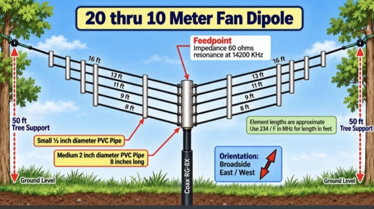
2. Starting measurements and target frequencies
Use 142.65 ÷ frequency in MHz for the approximate total half-wave dipole length in metres, or 71.325 ÷ frequency for one leg. The start lengths include a modest tuning margin. Insulation, height, bends, spacing and the other pairs change resonance, so calculated lengths are estimates.
| Band | Example target | Calculated leg | Start each leg | Starting pair total |
|---|---|---|---|---|
| 20 m | 14.200 MHz | 5.02 m | 5.25 m × 2 | 10.50 m |
| 17 m | 18.130 MHz | 3.93 m | 4.15 m × 2 | 8.30 m |
| 15 m | 21.250 MHz | 3.36 m | 3.55 m × 2 | 7.10 m |
| 12 m | 24.940 MHz | 2.86 m | 3.05 m × 2 | 6.10 m |
| 10 m | 28.400 MHz | 2.51 m | 2.70 m × 2 | 5.40 m |
These are example tuning targets, not operating frequencies reserved for this antenna. Choose your target within the part of each band you use. The 10 m pair is aimed around 28.4 MHz; it is not expected to have a good match across the entire 10 m band. This design does not include an 11 m CB pair.
The five pairs use 37.40 m of starting active wire. Buy approximately 45 m to allow for attachment tails, short terminal links and adjustments. For the simpler 20 / 15 / 10 m version, allow 23.00 m active wire and buy roughly 30 m. Do not subtract attachment allowance from the active dimensions.
3. Materials and tools
| Item | Quantity / practical specification |
|---|---|
| Antenna wire | About 45 m of UV-resistant insulated stranded copper, 1.5–2.5 mm². Use the same type for all pairs. |
| Current balun | One weatherproof 1:1 current balun with two balanced output terminals, specified for 14–30 MHz and your power and duty cycle. A 4:1 balun is not specified here. |
| Coax | 50 Ω outdoor coax, length to suit. RG-8X is a practical short-run option; a lower-loss cable can help on long runs, especially 10 m. |
| End insulators | Ten for five pairs, or six for the three-pair version. |
| Spreaders and ties | UV-resistant nonconductive material, smooth drilled holes, UV-rated ties or cord. Keep exposed wire and metal hardware clear of other pairs. |
| Support | Independent centre support, nonconductive end ropes, suitable anchor points and strain relief for coax. Support design must suit site loads. |
| Feedpoint hardware | Insulating plate or small weatherproof enclosure, stainless hardware, correctly sized ring terminals and short copper links if needed. |
| Tools | Tape measure, cutters, crimp tool, multimeter, antenna analyser or calibrated VNA, SWR meter, waterproof connector tape. |
4. Feedpoint connections — keep A and B separate
Connect every left-hand leg to output A and every right-hand leg to output B. If the terminals cannot safely hold five ring lugs, use two separate terminal strips joined to the outputs by short, straight links. Include each link in the measured electrical leg length. Do not wrap long pigtails into coils or use wire knots as electrical joints.
Carry mechanical tension on the insulating plate and strain-relief points, not the balun connector or soldered joints. Keep terminal hardware on the two sides apart. Balun DC continuity varies by construction; follow its maker’s check procedure rather than assuming any A-to-B DC reading indicates a fault.
5. Build and install it
- Plan the position. Allow approximately 11–12 m of clear span for the 20 m pair and centre hardware, plus end ropes. Support the centre and insulator ends independently. Select a position where the full antenna and supports cannot contact powerlines, even if they fall.
- Cut and label ten wires. Make two matching pieces for each row in the measurement table. Allow extra beyond the active length for tying to insulators. Mark each with band and left/right labels.
- Prepare the centre. Secure the balun to a suitable insulating support and make the two sets of connections shown above. Crimp or solder as appropriate to the terminals, protect the joint and provide separate strain relief.
- Arrange the pairs. Keep the longest pair uppermost. Use separate end ropes to fan the other pairs out below it. Maintain equal left/right geometry for each band. Wires must not cross or touch.
- Add spreaders where needed. As a practical trial layout, aim for roughly 150–300 mm separation between adjacent pairs away from the centre; this is adjustable spacing, not a proven universal optimum. Spreaders are insulating guides, not radiating elements or a rigid structural frame. Support them without bending or heavily tensioning the wires.
- Leave adjustable ends. Keep some spare wire at each end for lengthening. Fold back or temporarily secure tails for trials; remeasure after changing a fold because it still influences tuning. Cut permanently only when the complete installation has been checked.
- Raise it to the working height. A centre around 8–10 m is a practical starting installation where safe and supported, rather than a mandatory dimension. A flat horizontal arrangement generally radiates broadside to the wires; an inverted V changes the impedance and pattern. Keep ends out of reach and use an included V angle of at least about 90° for a V installation.
- Route the feedline. Run coax down from the balun roughly at right angles to the wires, with strain relief and a drip loop. Keep it away from individual legs. Weatherproof the outdoor coax connector and follow the enclosure maker’s sealing and drainage guidance.
Space matters: 150–300 mm spacing and the height above are proposed starting geometry, not W1TR’s verified dimensions. Keep a record of your actual spacing and height; changing either after tuning can move the SWR minima.
6. Tune it in its final position
Use an antenna analyser with the transmitter disconnected, or a calibrated VNA whose measurement reference plane is understood. With an SWR meter, use the lowest practical transmit power on a clear frequency within your permitted band and mode. Never connect a VNA while the radio is transmitting.
- Check connectors and wire identification first. Sweep each intended band and record the frequency of the SWR minimum, its SWR and the wire length per side.
- Begin with the longest pair: 20 m, then 17 m, 15 m, 12 m and 10 m. For the three-pair build use 20 m, 15 m, 10 m. After every adjustment, raise the antenna to the same working position.
- If a pair’s SWR minimum is below its chosen target, shorten both legs of that pair equally. If above, lengthen both equally. Adjust the relevant pair only, then recheck all bands.
- Near the target, try small changes of about 10–20 mm per end. Do not remove a large section on the first pass. Start with reversible end adjustments.
- As a rough estimate, new leg length ≈ current leg length × measured resonant frequency ÷ target frequency. For example, 5.25 m at 13.80 MHz gives about 5.10 m for 14.20 MHz. Interaction makes this an estimate; move part of the way, measure again and finish in small steps.
- Repeat the full sweep after the shorter pairs are adjusted. Aim for a useful operating-window match compatible with the radio, preferably 1.5:1 or lower near the target. Do not expect an identical match on every frequency or an exact 50 Ω impedance.
A tuner may be useful at a band edge, but it does not correct a poor connection, a hot balun or feedline loss. If adding a nearby pair destroys a previously good match, try more separation or a different fan angle, remeasure, and consider separating the WARC pairs onto their own feedline.
| Band | Final length per leg | SWR minimum frequency | SWR at target | Height / spacing notes |
|---|---|---|---|---|
| 20 m | ________ | ________ | ________ | ________ |
| 17 m | ________ | ________ | ________ | ________ |
| 15 m | ________ | ________ | ________ | ________ |
| 12 m | ________ | ________ | ________ | ________ |
| 10 m | ________ | ________ | ________ | ________ |
7. Common faults and what to check
| What you see | What to check next |
|---|---|
| High SWR on every band | Feedpoint wiring, coax connectors, damaged cable, wrong balun type, broken terminal or accidental contact between wire sets. |
| One pair tunes but its neighbour does not | Pair spacing, crossing wires, long feedpoint links and interaction. Temporarily disconnect the neighbour to diagnose, then reconnect and tune the complete antenna. |
| The analyser changes when coax is moved | Common-mode current, choke performance, coax routing and whether the antenna is still at the same height. Also check measurement calibration. |
| SWR changes in rain or wind | Wet connectors, water in coax, moving spreaders, slack wires or changing ground clearance. |
| Good SWR but weak signals | Lossy coax or balun, installation height, direction, propagation and antenna surroundings. Low SWR alone does not prove efficient radiation. |
| Balun becomes hot | Stop transmitting and check its frequency range, power/duty-cycle rating and load mismatch before continuing. |
8. Operating and installation notes
These are amateur HF bands. Transmit only with the appropriate licence and permissions. Keep people clear of radiating wires and high-voltage ends; set separation using a suitable RF exposure assessment for your actual power and duty cycle. Keep all supports and their fall radius clear of powerlines. Use site-appropriate lightning protection and disconnect equipment during storms.
References and original project
- DXZone: W1TR — 20 thru 10 Meter Fan Dipole
- W1TR original project (availability may vary)
- ARRL: half-wave dipole calculation and tuning
- ARRL: parallel dipole feedpoint principle
Club drawings and build layout prepared for Snacky’s Antennas · 2026. Calculations are starting estimates; this five-band layout has not been field-tested by the club.
Half-wave vertical · 27.355 MHz
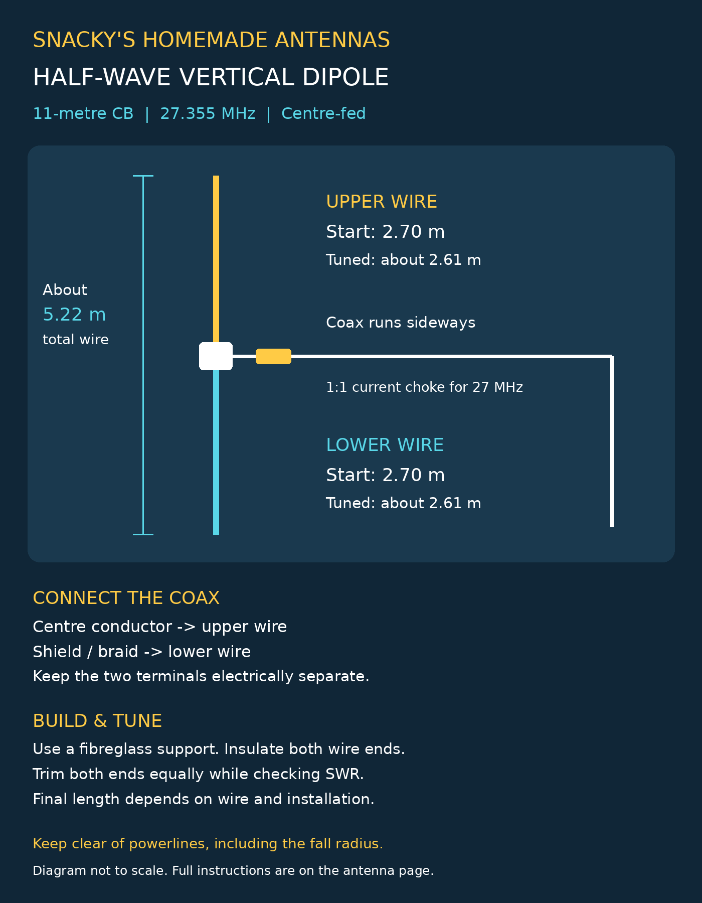
Start with two 2.70 m wire sections. The estimated tuned length is 2.61 m each; adjust both ends equally using an SWR meter in the final installation.
Connect the coax centre conductor to the upper wire and braid to the lower wire. Use a 1:1 current choke suitable for 27 MHz and route the coax sideways away from the antenna.
Use 1.5–2.5 mm² stranded copper wire. Support the lower tip at least 2 m above ground and allow roughly 7.5–8 m support height. Route the coax sideways for about 2.5 m if practical before bringing it down.
Check SWR at low power in the final position. If the SWR minimum is below 27.355 MHz, shorten both ends equally; if above, lengthen them. Make small adjustments and aim for 1.5:1 or better.
Keep the support and wires clear of powerlines, including their entire possible fall radius.
Baker Blaster Vertical Antenna
Snacky’s two-section aluminium upright concept for 11-metre CB, using a nominal 5.4 m Station Master-style length.
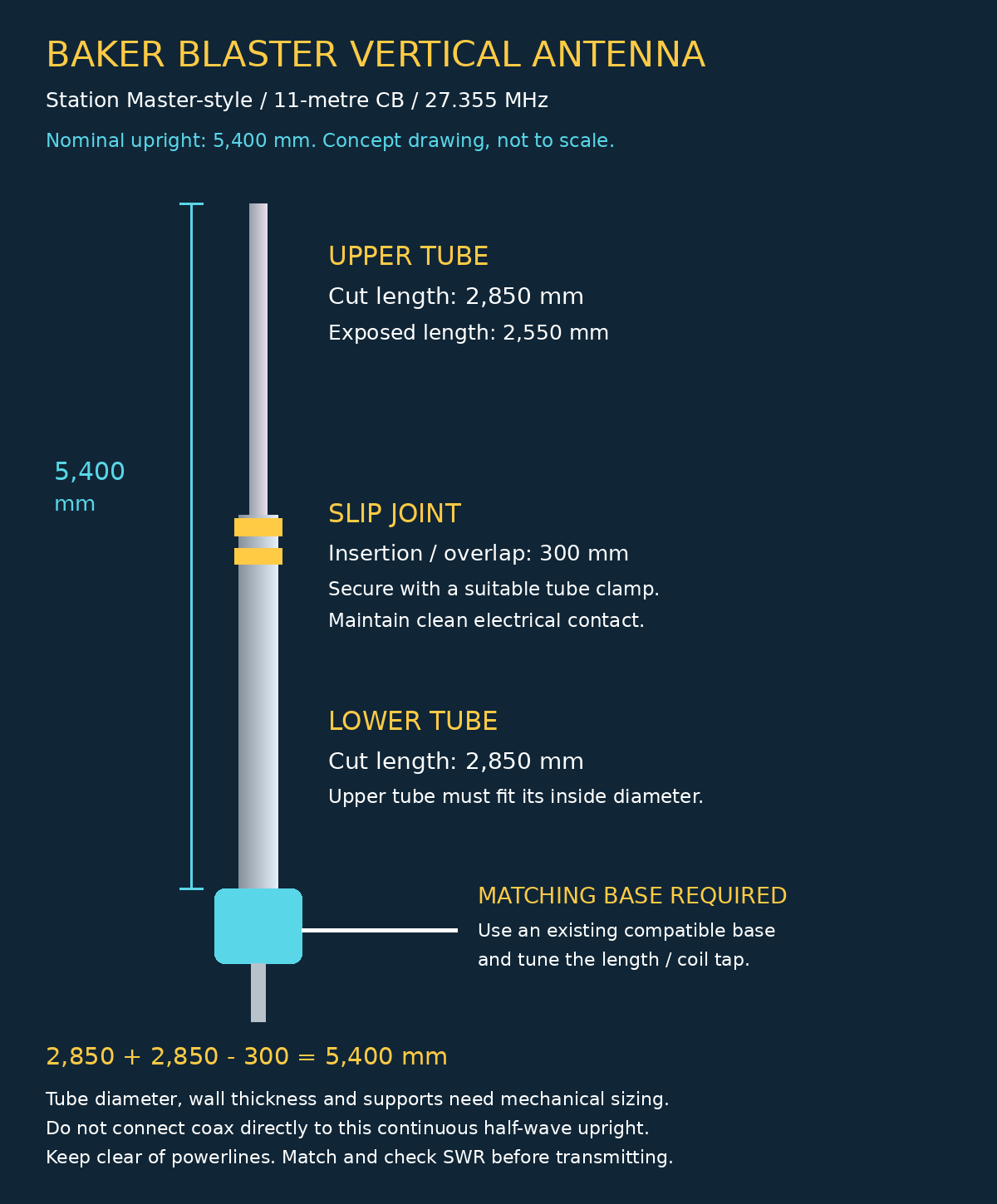
| Part | Measurement |
|---|---|
| Lower aluminium tube | 2,850 mm |
| Upper aluminium tube | 2,850 mm |
| Joint overlap | 300 mm |
| Assembled upright | 5,400 mm |
The upper tube slides into the lower tube with clean electrical contact and a secure clamp. Tube diameters, wall thickness, supports and the mounting arrangement must be sized before building.
A compatible matching coil/base is required. This is an upright concept, not a complete tuned antenna. Do not connect coax directly to the continuous half-wave upright. Adjust the length and matching arrangement using an SWR meter before transmitting.
The 5.4 m dimension is for the drawn upright; any base or mounting hardware adds to physical height. Commercial Station Master overall dimensions vary by model.
Open the Baker Blaster drawingQuarter-wave wire vertical · 27.355 MHz
A centre upright with four elevated radial wires. The radials form the other half of the antenna and connect to the coax braid.
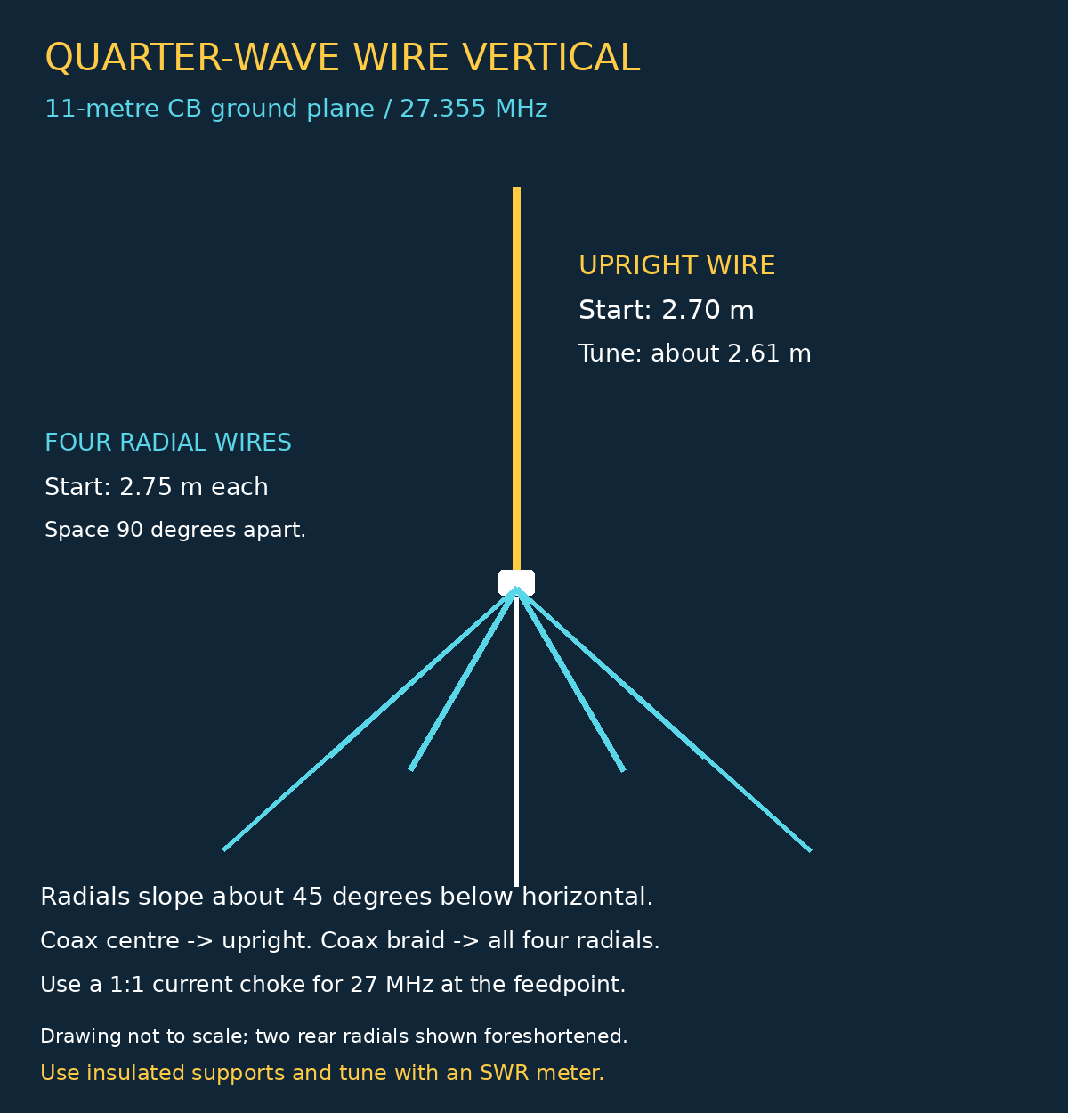
Materials and measurements
| Part | Specification |
|---|---|
| Upright wire | Start at 2.70 m; estimated tuned length 2.61 m |
| Four radial wires | Start at 2.75 m each |
| Wire | 1.5–2.5 mm² stranded copper; allow extra for ties |
| Feedline | 50-ohm coax, such as RG-58 |
| Choke | 1:1 current choke suitable for 27 MHz |
| Support | Fibreglass pole, insulated feedpoint and end insulators |
How to build it
- Measure each wire from its feedpoint terminal to its outer end. Leave adjustment allowance and extra wire for securing the ends.
- Support the upright vertically above the feedpoint. Connect it to the coax centre conductor.
- Connect all four radials together at the feedpoint and attach them to the coax braid. Keep this connection insulated from the upright terminal.
- Spread the radials evenly, 90 degrees apart when viewed from above. Slope each about 45 degrees below horizontal; secure its end using an insulator and nonconductive cord.
- Mount the feedpoint around 3 m above ground. With 2.75 m radials at 45 degrees, radial ends are about 1 m above ground, so keep the area inaccessible to people and animals while transmitting. The upright tip will be roughly 5.7 m high initially.
- Place the current choke close to the feedpoint and route the coax down the pole. Weatherproof the connections and provide strain relief.
How to tune it
Check SWR at low power across your intended operating frequencies with the antenna in its final position. Start long: insulation and nearby objects change the required length.
If the SWR minimum is below 27.355 MHz, shorten the upright; if above, lengthen it. Adjust about 5–10 mm at a time and recheck. Keep the radials equal in length. Their slope and length can also affect the match; aim for 1.5:1 or better rather than expecting a guaranteed reading.
Keep every part of the antenna and its possible fall radius clear of powerlines. Keep the wires clear of nearby metal and do not touch them while transmitting.
Open the quarter-wave drawing40 / 80 metre fan dipole
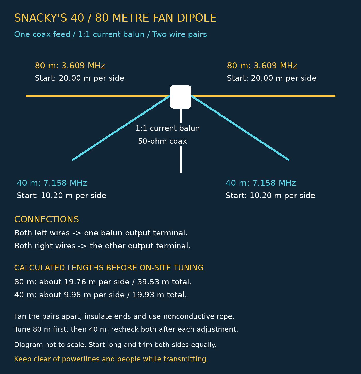
Two wire pairs share a single 1:1 current balun and 50-ohm coax feed. Targets: 7.158 MHz on 40 metres and 3.609 MHz on 80 metres.
Measurements and assembly
40 m: start with two 10.20 m wires; calculated tuned length is about 9.96 m per side. 80 m: start with two 20.00 m wires; calculated tuned length is about 19.76 m per side. Measure from the feed terminal to each wire end and allow extra for ties.
Use 1.5–2.5 mm² stranded copper wire. Connect both left wires to one balun output terminal and both right wires to the other. Choose a 1:1 current balun rated for 3.5–7.2 MHz and your transmit power.
Separate the pairs with nonconductive spreaders or separate end ropes. Use four end insulators and independently support the balun. Allow roughly 40 m of span plus end ropes for a straight installation; an inverted V is also possible. Run the coax away from the wires.
Tune 80 m first, then 40 m, and recheck both. Shorten both ends of the relevant pair equally if its SWR minimum is below the target; lengthen if above. Final lengths depend on height, insulation and interaction between the pairs. Use low power and keep wires clear of powerlines and people.
Open the fan dipole drawingCentre-fed horizontal CB dipole · 27.355 MHz
A horizontal half-wave dipole with a 1:1 current balun at its centre. Start with two 2.70 m wire sections; calculated tuned length is approximately 2.61 m each, or 5.22 m total.
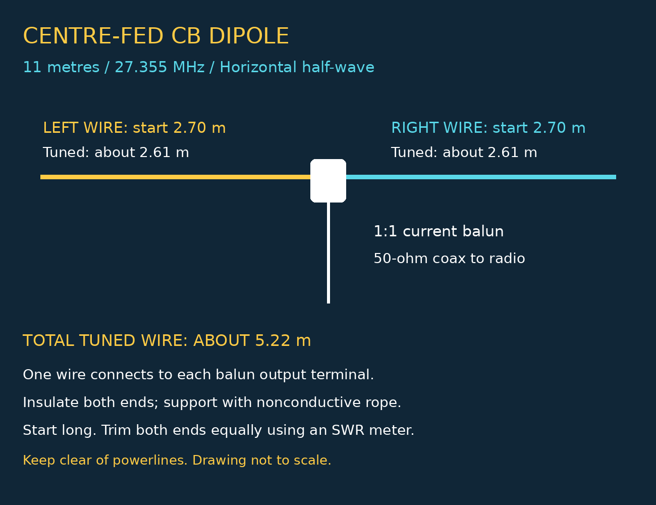
Connect one wire to each balun output terminal. Use a current balun rated for 27 MHz and your transmit power, 50-ohm coax, stranded copper wire and an insulator at each end. Support the centre and ends with nonconductive rope and allow additional wire for ties.
Keep the wires straight and in the clear. Run coax away from the centre at approximately right angles. This horizontal antenna is horizontally polarised; it can be less suitable for local contacts with vertically polarised CB antennas.
Tune in its final position at low power: trim both ends equally in small steps if the SWR minimum is below 27.355 MHz; lengthen if above. Final dimensions require measurement. Keep the antenna clear of powerlines and out of reach while transmitting.
Open the centre-fed dipole drawingSnacky’s centre-fed 40 / 80 metre trap dipole
One continuous wire run on each side of a centre balun, with one 7 MHz trap in each leg. Designed for tuning around 7.158 MHz and 3.609 MHz. These are starting dimensions for a build that must be measured and adjusted after installation.
Use two 40-metre traps, not 80-metre traps. Traps near 7 MHz separate the inner 40-metre sections from the outer extensions; on 80 metres the traps provide inductive loading. Traps near 3.6 MHz would be used to extend an antenna to a lower band such as 160 metres.
Measurements and materials
| Part | Quantity and starting specification |
|---|---|
| Centre to trap wire | Two × 11.00 m; reference build used 10.60 m per side |
| Trap to end wire | Two × 7.20 m; reference build used 6.70 m per side |
| Wire allowance | 36.40 m active wire initially, plus extra for attachment loops; buy about 40 m |
| Antenna wire | 1.5–2.5 mm² insulated stranded copper |
| Traps | Two identical parallel LC traps; construction below |
| Centre balun | One weatherproof 1:1 current balun covering 3.5–7.2 MHz, rated for the intended power and duty cycle |
| Feedline | 50-ohm coax, length to suit the shack; RG-213 is one option |
| Supports | Two end insulators, insulated trap strain relief, centre support and UV-resistant nonconductive ropes |
Measure the inner wires from the balun output terminals to the inner trap terminals, and outer wires from the outer trap terminals to the free wire ends. The starting wire run totals 36.40 m, excluding trap bodies, centre hardware and end ropes. The reference dimensions total 34.60 m of wire; they are not guaranteed final lengths. Different traps require different outer lengths.
Build the two traps
This uses PA0FRI’s documented LC trap recipe: each coil has 16 close-wound turns of insulated 1.5 mm² installation wire on a 32 mm outside-diameter PVC former, with about 49 mm winding length. Connect a 100 pF RF-rated high-voltage capacitor across the coil ends; the documented version uses a 7–10 kV capacitor and resonates around 7–7.2 MHz. Wire insulation thickness affects the result.
- Prepare two formers about 100 mm long, allowing room outside the winding for attachments. Wind matching coils and keep capacitor leads short.
- Join one capacitor lead to each coil end. These same two junctions are the trap terminals: one faces the balun and the other faces the outer wire. Coil and capacitor are in parallel, not in series.
- Support wire tension through an insulating bracket or insulator. Do not let the capacitor or soldered leads carry the antenna’s weight.
- Measure each trap using a dip meter or a VNA with loosely coupled loops. Start near 7.1 MHz and match the pair within about 20 kHz. Spread turns slightly to raise resonance; compress to lower it. Turn count alone does not establish the frequency.
- Enclose the traps in weather-resistant nonmetallic housings with drainage at the lowest point. Keep capacitor clear of the winding and terminals, secure all parts, then remeasure after enclosing them.
Alternatively use a matched, power-rated pair of commercial 40-metre traps and follow their maker’s wire dimensions. A capacitor’s voltage marking alone does not establish the completed trap’s safe RF power rating.
Assemble and install
- Connect one inner wire to each balun output terminal. Connect each inner wire to a trap, then attach an outer wire to that trap’s remaining terminal.
- Fit end insulators and ropes. Leave adjustable folded-back ends so you can lengthen wires again. Keep both legs symmetrical.
- Support the balun independently. Install horizontally or as an inverted V; a centre around 10–12 m high and an included V angle of at least 120° are practical starting choices when the site allows. Keep ends at least 3 m high and out of reach.
- Attach the coax to the balun input and route it down, away from the wires at roughly right angles. Provide strain relief and weatherproof the connector.
Tune 40 metres first, then 80 metres
- With the complete antenna at its final height, sweep 40 metres using an analyser. Adjust both inner sections equally toward a minimum near 7.158 MHz: shorten if the minimum is too low; lengthen if too high. Keep the traps attached while tuning.
- Then sweep 80 metres. Adjust only the two outer sections equally toward 3.609 MHz. For the Hervey Bay 3.615 MHz net, choose 3.615 MHz instead and measure whether both frequencies give an acceptable match.
- Make small adjustments, beginning with folded-back wire rather than irreversible cuts. Recheck both bands after every change. If there is no clear minimum or the match stays poor, inspect the traps, connections, balun and nearby metal before cutting more wire.
- Confirm SWR at low transmit power before increasing power. Aim for 1.5:1 or better at your selected frequencies; a tuner may be needed elsewhere in the bands.
Band coverage
Intended bands: 40 metres and 80 metres. Measure the usable SWR range of your finished installation. Especially on 80 metres, traps reduce bandwidth: do not expect a low SWR across the whole band. Other HF bands and 27 MHz CB are not promised by this design.
Keep antennas, ropes, supports and their full possible fall radius clear of powerlines. Do not touch wires or traps while transmitting; keep people and animals away from the wire ends.
Trap recipe and reference dimensions: PA0FRI’s 7 MHz LC trap construction. Trap operation and bandwidth: VK4ADC’s antenna trap notes. Starting cut allowances and installation guidance above are adaptations for this build, not a tested finished antenna.